← All Products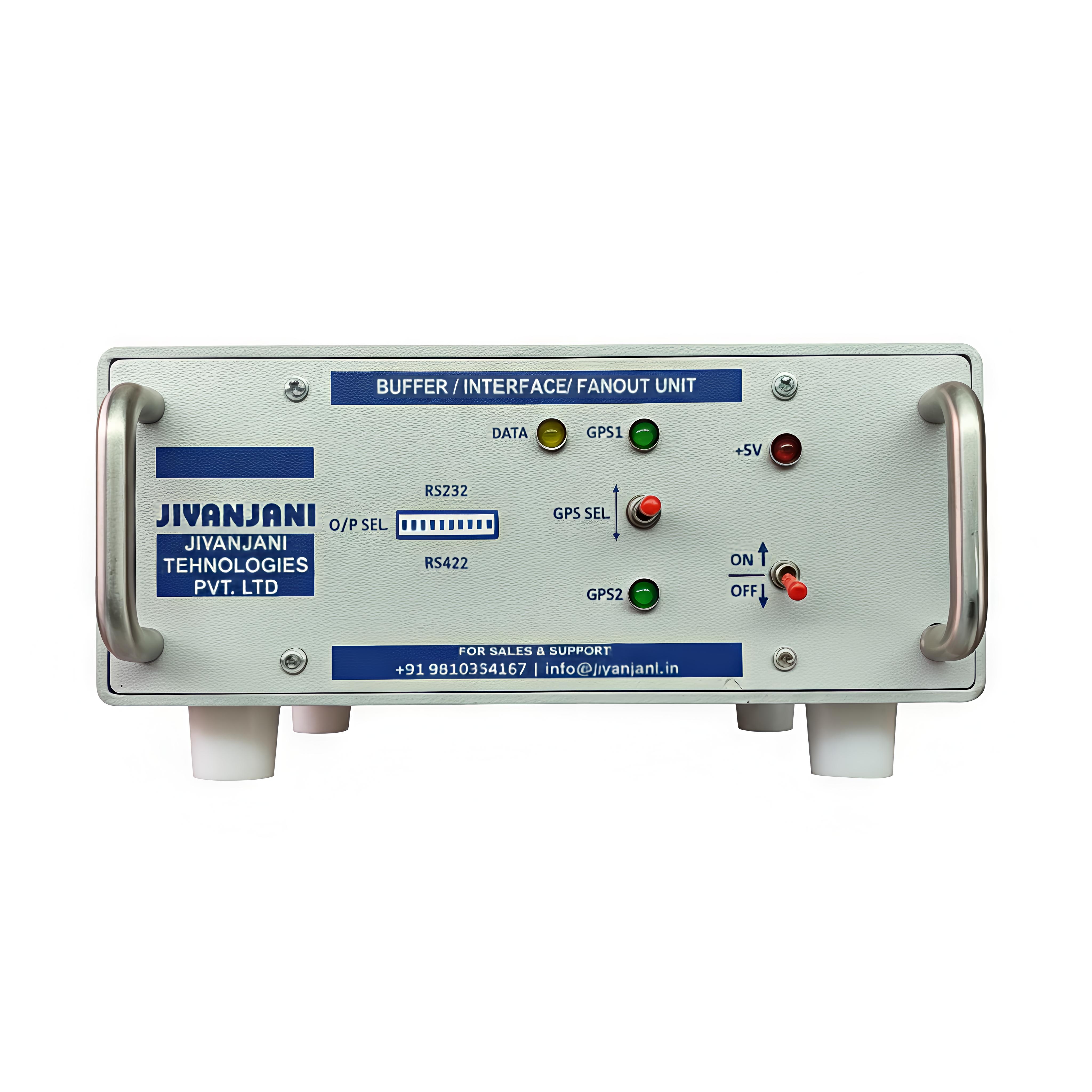
MPN: JNJBUF001
Fanout Cum Buffer Unit
A configurable serial data distribution unit with two independent inputs and eight outputs. Each input feeds four outputs, with RS232 or RS422 formats selected individually through front-panel DIP switches.
Technical Specifications
| Parameter | Specification |
|---|---|
| Part number | JNJBUF001 |
| Inputs | Two independent user-configurable RS422 / RS232 ports |
| Outputs | Eight user-configurable RS422 / RS232 ports; four outputs from each input |
| Configuration | 10 front-panel DIP switches; switches 1-8 select output formats, switches 9-10 select input formats |
| Discharge protection | ±10 kV |
| Data line protection | Short circuit protection |
| Enclosure | Powder-coated aluminium and stainless steel; anti-rust and anti-vandal properties; table mount |
| Maximum dimensions | 190 × 240 × 100 mm; compact, lightweight and portable |
| Power indication | Front-panel LED indicates power availability |
| Connectors | Corrosion-resistant aluminium / nickel / bronze alloy; Amphenol / Allied / equivalent. 5-pin female chassis-mount inputs and 5-pin male chassis-mount outputs; cable-end connectors supplied. |
| Power supply | 220 V AC, 50 Hz, single phase; over-current and over-voltage protection, with electrical isolation against high-voltage surges |
| Environmental specification | IEC 60945 compliance and supplier certificate required by the technical specification |
| Design documentation | Schematic, bill of materials, PCB Gerber files and drawings to be shared with WESEE for validation / concurrence before development |
RS232 & RS422 Electrical Characteristics
| Parameter | RS232 | RS422 |
|---|---|---|
| Maximum driver voltage | ±25 V | -0.25 V to +6 V |
| Driver output signal (loaded minimum) | ±5 V to ±15 V | ±2 V to ±6 V |
| Driver output signal (unloaded maximum) | ±25 V | ±6 V |
| Driver load impedance | 3000-7000 Ω | 100 Ω |
| Maximum driver current in high-Z state | ±6 mA at ±2 V | ±5 µA |
| Maximum slew rate | 30 V/µs | N/A |
| Receiver input voltage range | ±15 V | 0 to 0.8 V / 02 to 06 V (as listed in the PDF) |
| Receiver input sensitivity | ±3 V | ±200 mV |
Port Configuration
Connect serial inputs and outputs to the rear-panel connectors. Select RS232 or RS422 independently using the front-panel DIP switches. Each input feeds four output ports.
| Input | Format | Pin A | Pin B | Pin E | DIP switch | Position |
|---|---|---|---|---|---|---|
| I/P 1 | RS232 | RS232 signal | — | Signal GND | 9 | UP |
| I/P 1 | RS422 | RS422 +ve | RS422 -ve | — | 9 | DOWN |
| I/P 2 | RS232 | RS232 signal | — | Signal GND | 10 | UP |
| I/P 2 | RS422 | RS422 +ve | RS422 -ve | — | 10 | DOWN |
| Outputs | Format | Pin A | Pin B | Pin E | DIP switches | Position |
|---|---|---|---|---|---|---|
| O/P 1-8 | RS232 | RS232 signal | — | Signal GND | 1-8 respectively | UP |
| O/P 1-8 | RS422 | RS422 +ve | RS422 -ve | Signal GND | 1-8 respectively | DOWN |